Production Systems
Offshore Production Platforms
General Corrosion


Fatigue


Inspection


Gathering Systems, Tanks, and Pipelines
Sweet Gas


Sour Gas
Oil Wells
External Corrosion
Storage of Tubular Goods
Inspection
Cleaning
Application of Protective Coatings
Continuing Maintenance
Duplex Stainless Steel Wirelirie
API 5AC, Grade L-80, Casing Failure
Rupture of a Sour Gas Pipeline
Industry Standards
Materials and Design Specifications
REFERENCES
Most failures in the SACROC unit were due to rod breakage. Inhibitor programs were satisfactory in some wells, but many did not respond. Plastic-coated rods and spray metal coating with type 316 stainless steel helped to alleviate the problem. The use of fiberglass rods in the upper 70% of the string, along with stainless steel coated rods on the bottom, reduced rod breakage to an average of 1.1 per well per year.
Tubing leaks can be controlled with coatings and the use of 9Cr-lMo and 13% Cr steel tubing where inhibitors fail to control. Flow line corrosion can be controlled by the use of fiberglass-epoxy lines. Other systems have experienced problems similar to those found in the SACROC unit and have successfully controlled corrosion with the previously described methods. Inhibitor selection by field testing with linear polarization techniques has resulted in improved protection of producing wells. The linear polarization technique is also used in routine monitoring, along with coupons, iron counts, and caliper surveys.
Offshore Production Platforms
Offshore structures have been in service in various parts of the world for over 40 years. Early experience was in the Gulf of Mexico with water depths of less than 90 in (300 ft). Technology has advanced to the point at which the largest drilling and production platform stands in more than 305 m (1000 ft) of water.
A platform consists of three parts. The jacket is a welded tubular space frame that is designed as a template for pile driving and as lateral bracing for the piles. The piles anchor the platform permanently to the sea floor and carry both vertical and lateral loads.
The superstructure is mounted on top of the jacket and consists of the deck and trusses necessary to support operational and other loads. Generally, platforms are carried from the fabrication yard to the site on a barge and are either lifted or launched off the barge into the water. After positioning the jacket, the main piles are driven through the legs of the jacket, one through each leg. Other piles, known as skirt piles, can be driven around the perimeter of the jacket as needed.
Current design and fabrication practices related to fixed steel offshore structures can be found in industry publications, professional journals, and the proceedings of technical conferences. The most basic American document on this subject is API RP-2A (Ref 73), which was first issued in October 1969 and has had many subsequent editions. Because American experience has been mainly in the Gulf of Mexico , API RP-2A generally represents that experience.
General Corrosion
Marine structures operate in a complex environment that can vary significantly according to site location and water depth. Figure 25 shows the four main platform corrosion zones: soil, seawater, splash zone, and marine atmospheric.
Marine atmospheric corrosion problems occur on the portion of the jacket above the splash zone and on the superstructure. Exposed steel surfaces suffer corrosion from an environment of water condensation, rain, salt precipitation, sea mist, and oxygen. Corrosion rates can range from 0.05 to 0.64 mm/yr (2 to 25 mils/yr). Corrosion is particularly severe at crevices and sharp-edged areas, such as skip-welded plates and steel structural shapes. Attention to design and fabrication details can eliminate most of these problem areas.
Atmospheric corrosion can be minimized by using coatings or by substituting nonferrous materials, such as copper alloys, nickel alloys, and FRP for steel components. Care must be taken not to create a galvanic-corrosion problem by coupling dissimilar metals. Table 5 gives a summary description of several marine zones and the characteristic behavior of the steel.
The splash zone is defined in NACE RP-0 1-76 (Ref 76) to be the area of the platform that is alternately in and out of the water because of tides, winds, and sea. It does not include surfaces that are only wetted during major storms. The splash Zone of the platform can cover an interval of 1.5 to more than 12 in (5 to more than 40 ft), depending on location. Generally, the area of the platform that suffers the most severe steel corrosion is the splash zone, as shown in Fig. 26. Common methods of controlling corrosion in the splash zone include applying coatings, increasing jacket wall thickness by 6.4 to 19 mm (0.25 to 0.75 in.) in the splash zone to compensate for the higher corrosion rates, or applying a Monel alloy wrapper.
Corrosion of steel in seawater is a function of water salinity, temperature, oxygen content, velocity, resistivity, and chemistry. Table 6 summarizes the effects of these and other factors on the corrosion of steel in seawater. Several of the variables controlling corrosion are interrelated. As an example, Table 7 demonstrates the relationship between temperature and oxygen solubility in seawater. The lower the temperature, the higher the solubility. As temperature or oxygen levels increase, corrosion rates will increase. To control seawater corrosion, the steel jackets are normally cathodically protected. The types of cathodic protection systems used are sacrificial anode, impressed current, or a combination of the two (see the discussion of cathodic protection in the section Corrosion Control Methods” of this article). Occasionally, cathodic protection will be used in combination with coatings.
Not only does cathodic protection control corrosion but it also eliminates concern over a corrosion fatigue failure of the jacket. Corrosion fatigue is discussed in more detail below. Typical cathodic protection system design parameters are given in Tables 8 to 10.
The major platform components below the mudline are the jacket piles. In general, steel corrosion rates are low below the mudline. The exception is when the mud contains sulfate-reducing bacteria. Because the piles have electrical continuity with the jacket, the jacket cathodic protection system will normally protect the piles from corrosion in saline muds.


Fatigue
Corrosion is of particular concern for the platform tubular welded joints, called nodes. The nodes are areas of high stress due to their complex geometries (Ref 78-80). The points of maximum stress in the nodes occur at the toe of the welds joining the tubular members. Cyclic stresses result from environmental factors, such as waves, tides, and operating loads. Platforms are designed to handle both a maximum stress and fatigue. The maximum stress is usually based on 100-year storm conditions. Platform fatigue life is based on an environmental stress distribution analysis, along with analysis of the stress cycles (Ref 81). Fatigue design curves have been published by the American Welding Society, British Standards Institute, American Petroleum Institute, and Det Norske Veritas.
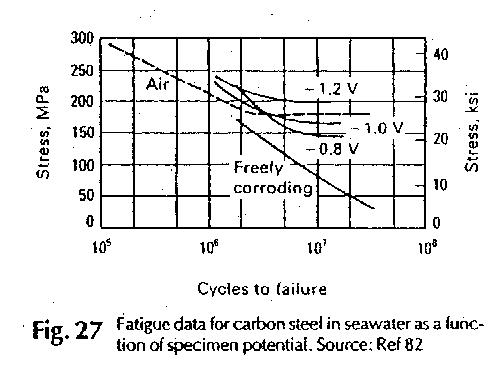
Corrosion can reduce the fatigue life of platform anodes. Galvanic corrosion of nonstress-relieved welds and pitting corrosion can result in stress raisers. Therefore, corrosion can lead to the initiation of cracks and can increase the growth rate of existing cracks, reducing fatigue life. The fatigue life of steel exposed to seawater is shorter than that of steel exposed to air because of corrosion fatigue. As Fig. 27 illustrates, steel growth rate of existing cracks, reducing fatigue life. The fatigue life of steel exposed to seawater is shorter than that of steel exposed to air because of corrosion fatigue. As Fig. 27 illustrates, steel immersed in seawater does not exhibit an endurance limit. Because there is no endurance limit, unprotected steel exposed to seawater is susceptible to fatigue failure even at low stress levels after long-term cyclic service. An API study discussed crack initiation in smooth, notched, and welded specimens and summarized a number of earlier investigations (Ref 83). Table II ranks according to importance the various seawater environmental variables influencing corrosion fatigue crack initiation of carbon steel. The corrosion fatigue effects are eliminated by the application of cathodic protection (Fig. 28).


Inspection
The purpose of periodic inspection is to ensure that the structure is fit for continued service. Through the inspection program, a company is protecting its personnel and assets, in some locations of the world, governmental bodies have established legislation or code agencies that determine minimum inspection requirements. Elsewhere, the operator decides on the minimum inspection needs for the platform.
Inspection is required even though platforms are designed and constructed to conservative codes (Ref 84). Inspection allows confirmation that the codes are adequate. It should be noted that the codes represent the best experience and knowledge at the time they are written. Often, the design parameters must be extrapolated for use in new frontier environments that were not foreseen when the codes were written. Inspection results provide the information necessary for updating the code test account for these new environments. Inspection of the platform jacket is designed to assess corrosion, fatigue cracks joint and brace failure, impact damage, marine growth, scour, and debris accumulation. Inspection techniques include visual inspection by divers and remote operated vehicles, still and video photography, ultrasonic thickness measurements, cathodic potential surveys, magnetic-particle inspectjon, and vibration frequency attenuation.


Gathering Systems, Tanks, and Pipelines
Gathering systems are defined as all production facilities from the wellhead choke (or pumping T) to the sales point (oil and/or gas); subsystems include flow lines, separation, and dehydration. Gas processing will be reviewed briefly. Sulfur plants (conversion of H2S to elemental sulfur), gas transmission lines and oil pipelines, gasoline plants, and water-handling facilities for disposal are beyond the scope of this discussion, although the same principles will apply. Internal and external corrosion alleviation systems will be reviewed, respectively.
Internal corrosion is dependent on the composition, temperature, pressure, and flow regime of the produced fluids. Although the general direction of the effect of each of these items is known, and the interrelationship of all these effects is not well understood. In short, corrosion alleviation is not an exact science (Ref 85).
A natural gas reservoir is a reservoir that, under initial conditions, is a single, gaseous hydrocarbon phase. If this gaseous phase contains hydrocarbons that are recoverable as liquids on the surface, the reservoir is a gas condensate reservoir. A gas well is a well that produces fluids from a gas or gas condensate reservoir.
An oil well is a well that produces from a hydrocarbon reservoir that is either a two-phase system or a single liquid phase (Ref 86). Because produced fluids essentially determine the internal environment (weather conditions and process design can affect temperatures and pressures), gathering systems for gas wells and oil wells will be discussed separately.
From both a metallurgical and corrosion viewpoint, it is important to distinguish between sweet gas wells and sour gas wells. If the partial -pressure of H2S is greater than 0.34 kPa (0.05 psia), the gas stream is sour and materials that resist sulfide-stress cracking must be used. The latest revision of NACE MR-Ol-75 (Ref 5) lists materials that are recognized to have acceptable resistance to sulfide-stress cracking.
The determination of whether H2S or CO2 corrosion mechanisms will predominate is not as simple. Early investigators believed that CO2 had a synergistic effect on H2S corrosion. Subsequent investigators indicate that it is the ratio of partial pressures of CO2 to H2S that controls the corrosion mechanism. According to studies by one researcher, unless the ratio of CO2 to H2S partial pressure is greater than 500, the corrosion mechanism is dominated by H2S (Ref 87). More recent investigations suggest that at some temperatures when the ratio of CO2 to H25 partial pressure is plotted versus corrosion, there is a sharp discontinuity as the ratio is reduced when the controlling mechanism changes from CO2 to H2S, but not always at 500. At other temperatures, the data suggest that the change in corrosion mechanism from CO2 to H2S controlled as the ratio of partial pressure of CO2 to H2S is reduced as a continuous function, rather than the above step function (Ref 88).
Because CO2 corrosion is usually more severe than H2S corrosion at cool conditions and because most production facilities are relatively cool, CO2 corrosion should be considered whenever the ratios of CO2 to H2S partial pressures are greater than 100.
Oxygen is never present naturally in oil and gas reservoirs, and without exception, it is preferable to keep it out rather than to alleviate its corrosion effects.
Sweet Gas
With regard to CO2 corrosion alleviation in flow lines, there are several choices. First, low-alloy steel with a corrosion allowance can be used; a monograph establishes the maximum corrosion rate for CO2 (Ref 89). Velocity may also be important; several authors have suggested that there is a critical velocity above which CO2 corrosion is very difficult to control (Ref 90). Again, more recent data suggest that at the same temperature, pressure, composition, and pH, the CO2 corrosion-velocity relationship is a continuous relationship rather than a step function (Ref 88). If the flow lines are welded, the operator should be certain that the weldments are at least as corrosion resistant (and where H2S is present, as cracking resistant) as the pipe body.
A second choice is to use corrosion-resistant materials, alloys, or coatings. With regard to CO2, either type 316 stainless steel or duplex stainless steel will provide sufficient internal corrosion resistance. If H2S is present, then NACE MR-0 1-75 (Ref 5) must be followed. Type 316 stainless steel is subject to chloride SCC at elevated temperatures, and both alloys (type 316 stainless steel and duplex) may be subject to external pitting corrosion or crevice corrosion. Both alloys also require special care from the time they are installed to the time they are put into service. Oxygen and perhaps bacteria will result in pitting corrosion. Metallurgical solutions, if properly executed, result in permanent low-maintenance corrosion alleviation systems.

A third choice is to internally line low-alloy steel pipelines with a corrosion-resistant material. These systems may have advantages over solid corrosion-resistant alloys. First, they may be less expensive, and second, the alleviation of external corrosion problems of low-alloy steel is well understood (years of history with large quantities of pipelines) and less sophisticated. There are two disadvantages) and less sophisticated. There are two disadvantages. Special welding procedures are required, and when the metallurgical coating is not bonded, buckling of the liner may occur, particularly in bends. This buckling will inhibit the use of tools pumped through the flow line.
Table 11 Summary of major variables influencing the corrosion fatigue crack initiation behavior of carbon steels in seawater

Two other internal coatings are also commonly used: organic polymers (plastic coatings) and cement linings. Both systems can be economic successes. However, both systems have difficulty in maintaining corrosion resistance at the joints, are difficult to install holiday-free, have limited life, and may suffer disbondment and failure when the pipe is improperly handled or distorted. The plastic coatings are permeable to the produced fluids, and eventually (3 to 5 years), the corrosive fluids will permeate the coating. The resulting corrosion products cause disbonding of the coating and complete loss of its corrosion resistance. Cement linings are thicker and less subject to produced fluid penetration than plastic coatings. They are heavy and may have limited resistance to acids.
A final alternative is to use nonmetallic pipe materials such as FRP or polymerized hydrocarbons. The advantage of these materials is their complete resistance to corrosion. Their disadvantages are low allowable temperatures, low fatigue resistance, low strength, low resistance to mechanical damage, and high combustibility. They also have problems with joint integrity. Finally, they may be vulnerable to attack from the produced fluids (CO2 may dissolve the resins from fiberglass pipe, and unsaturated hydrocarbons may dissolve the polymerized hydrocarbon pipes).
An alternative to corrosion-resistant materials is to use corrosion inhibition. If corrosion inhibition is used to protect the gas well downhole tubulars, the same system will protect the how lines if the flow lines are properly designed. The flow lines should be sized to ensure turbulent flow at a velocity that is not significantly higher than that present in the tubing.
Turbulent flow will ensure inhibitor contact with the entire internal pipe surface, and limited velocities (flow lines are cooler than gas well tubulars) will ensure that flow line conditions are not significantly more corrosive than the gas well tubulars. Because the economic consequences of down-hole tubular failures are usually much greater than flow line failures, designing the surface flow lines to utilize downhole inhibition is not used, then surface inhibition can be used to protect the flow lines. In low velocity/low liquid flow regimes, periodic inhibition with a technique that inhibits the entire internal surface can be successful. For higher velocities (turbulent flow) and/or high liquid content, continuous inhibition will probably be necessary.
Separation and dehydration facilities offer fewer alternatives. Because inhibitors usually stay in the liquid phase in multiphase systems and usually in the hydrocarbon phase if one is present, reliable inhibition of the vapor space is impossible. Fortunately, corrosion is usually not severe, because only water of condensation is present. For very severely corrosive environments, such as wet C02, type 316 stainless steel or type 316 stainless steel internal cladding is usually used. For normal gas production with C02, low-alloy steel, combined with a corrosion allowance and monitoring, is used.
For gas dehydration systems, low-alloy steel with corrosion allowance is normally sufficient when combined with pH control of the glycol. For gas streams high in CO2 concentrations, some operators have found it necessary to internally clad the wet gas portions with type 316 stainless steel.
Sour Gas
Sour gas wells present a more difficult problem. First, all materials must be resistant to sulfide-stress cracking. It is essential that no equipment suffer catastrophic cracking failures. General corrosion is less severe for H2S than for CO2 at the lower temperatures usually encountered in flow line systems, and H2S corrosion is not velocity dependent. As long as sufficient liquid hydrocarbon is present, corrosion is usually minor. When hydrocarbon liquids exceed 100 barrels per 28 300 m (1,000,000 ft ) of gas, when the water content of the liquid phase is less than 10%, and when the flow is turbulent (to avoid water phase in the bottom of the line), no serious corrosion problem should be expected. In cases in which the above conservative criteria are not met, inhibition may be necessary. The same rationale in regard to the use of inhibitors in flow lines with CO2 applies to flow lines for H2S. Inhibition systems that protect downhole tubulars will protect the flow lines if the entire internal wall is inhibited. Processing facilities, gas separators, and sweeting systems (sulfinol, amines, and so on) are usually constructed of low-alloy steel with a corrosion allowance and are regularly monitored.
Oil Wells
Oil wells, as previously defined, are wells that produce from a hydrocarbon reservoir that is either two-phase or a single liquid phase. Oil well flow line corrosion is much easier to handle than gas well flow line corrosion. First, sour oil wells are usually beyond the scope of NACE MR-0l-75 (Ref 5). Second, CO2 corrosion is seldom, if ever, a problem. Most crude oils (and associated gas) either contain no CO2 or sufficient H2S for H2S to be the controlling corrosion mechanism. Corrosion problems are often minor until water-cuts approach 30%. Normally, when water-cuts are high enough for saltwater (with or without H2S) corrosion to be a problem in the flow lines, corrosion will be more severe on the downhole tubulars, and the inhibition system protecting the tubulars will protect the flow lines. Flow lines with stratified flow that allow free water to flow or stagnate in the bottom of the flow lines may suffer corrosion problems. In these cases, inhibitors in the oil phase from the well may not help. This problem is successfully handled by frequent pigging in order to clear the flow lines of water; to clean out sediment, which will foster crevice corrosion; and to distribute inhibitor over the entire internal surface.
Gas separation facilities and free water knock outs arc usually made of low-alloy steel. Free water knock outs are often internally coated with an organic coating. Coatings, if properly applied to clean dry surfaces, may extend the vessel life a few years. Generally, coatings do not remain holiday-free for very long in saltwater service. The only other alternative to low-alloy steel with corrosion allowance and internal coating is a corrosion-resistant material. The low corrosivity, however, does not justify the cost of a corrosion-resistant alloy, either solid or internally clad. The combination of size and pressure usually eliminates the use of materials such as fiberglass.
Corrosion problems can be severe in saltwater-handling facilities, although they are usually mild to moderate. Corrosion alleviation systems are limited to cathodic protection, organic coatings, and, occasionally, nonmetallic vessels.
Crude oil is usually dehydrated by using gravity separation of the lighter oil from the unwanted water. Heat, chemicals, and electric fields are often used to accelerate the gravity separation. The separation vessel should not experience severe corrosion if the system is kept oxygen-free. Cathodic protection is only partially successful for the vessel, because only the water-wet portion is protected and the oil/water interface fluctuates. The heating coils often suffer more severe corrosion than the vessel body. As long as these coils are in the water portion of the vessel, well designed and maintained cathodic protection systems are successful in alleviating corrosion of the heating surfaces. When large tanks are used, galvanizing significantly prolongs the tank life in the absence ofH2S. Hot-dip galvanizing is considered to he the most effective treatment, but it is limited to bolted tanks. The bolted tank gaskets, in turn, limit the temperatures at which the vessel can be operated.
The gas separated from the oil is low pressure and can be safely handled with low-alloy steel with a corrosion allowance. The storage of dehydrated oil (usually about 1% H2O) poses no internal corrosion problems, except in the tank bottom, where salt water will accumulate.
External Corrosion
External corrosion can also be a serious and costly problem. In wet or corrosive soil, low-alloy steel flow lines should be coated. There are a variety of successful coating systems. Usually, the external coating system consists of two parts: a mastic that coats and protects the pipe and a coating or wrapping that protects the mastic. If the flow lines are needed for long periods of time, then the external coating should be supplemented with cathodic protection. Surprisingly, it is probably more important to cathodically protect corrosion-resistant alloy flow lines than low-alloy steel flow lines. The corrosion-resistant alloys-type 316 stainless steel or duplex stainless steel-are subject to crevice corrosion in the presence of oxygen. Because these stainless steel lines are much more expensive than low-alloy steel lines, they cannot be allowed to fail by external corrosion. Therefore, external cathodic protection of these flow lines is essential when they are buried or submerged. To reduce the current level required for protection, the corrosion-resistant alloy, like the low-alloy steel pipeline, is usually externally coated.
The other components of the gathering system are the storage tanks, gun barrels, and surge tanks. As has been reviewed earlier, these vessels all internally accumulate salt water on the bottom. Similarly, these tank bottoms are all subject to external corrosion. Because the tank bottoms are relatively thin and may suffer internal corrosion, they should be protected from external corrosion. Therefore, in wet environments or where long service is needed, cathodic protection of tank bottoms should be considered. For piping and vessels above ground, painting is the accepted method of protecting against corrosion.
Monitoring
Monitoring is an essential part of any corrosion alleviation system. No corrosion alleviation system is completely reliable, and in many cases failure can be catastrophic, both from a personal safety perspective and from an environmental and/or economic perspective. There are a wide variety of inspection techniques. The thoroughness and frequency of the monitoring must be weighed against the consequences of failure, and the type of monitoring must be tailored to the particular system. Certainly, it is more catastrophic to have a high-pressure sour gas vessel failure than an atmospheric saltwater tank failure.
Flow lines can be monitored with calipers that are pumped through the line, x-rayed, or, where warranted, cut open and inspected. Vessels can be visually and/or ultrasonically inspected. When ultrasonic inspection is used, reference points are usually permanently fixed to the vessel external wall so that the ultrasonic test is conducted at the same location each time.
Storage of Tubular Goods
Tubular goods used in oil-producing and drilling operations are sometimes stored outdoors or in areas where internal storage is conducive to corrosion. This is particularly true in coastal regions and industrial areas in which acid gases and pollutants are present as well as in oil fields that produce hydrogen sulfide.
Oxygen corrosion, or rust, is aggravated by the deposition of salt from marine environments, such as that encountered in wind-driven spray on offshore platforms, and airborne salt in coastal areas. Pipe yards situated close to the beach are particularly susceptible to severe atmospheric corrosion. In warehouses and under sheds, the presence of industrial pollutants such as SO2, oxides of nitrogen, and other gases will initiate corrosion attack and increase rusting when they react with moisture in the air or on the pipe.
Even in areas of relatively low salt and pollution content, severe corrosion may occur if the relative humidity is high. The pipe will cool off during the night, and dew will fall, covering the pipe with a conductive layer of electrolyte. The rust that is already on the pipe is hygroscopic and will remain moist after the free water has evaporated. This leads to concentration cell attack and severe pitting. Pit depth and size are of particular importance, because failures may occur when the pipe is put into service under pressure.
Inspection
Before being put into service, tubular goods that have been stored for any length of time should be inspected. Particular attention should be given to the following areas:
• External rusting. The percent of surface area covered by rust should be recorded
• Presence of mill scale, lacquer-type mill coatings, or other temporary coatings. This is important, because areas not covered may corrode, while protected areas may set up concentration cells and accelerate localized corrosion
• Internal corrosion: The interior of the pipe should be inspected for rusting and pitting
• Condition of threads: Threads should be examined to determine if corrosion damage has occurred that could prevent proper makeup
Cleaning
After inspection, the pipe should be cleaned prior to applying any protective coatings. The pipe can be cleaned mechanically or with acids or rust dissolvers.
If the pipe is used, or has been stored in marine or industrial environments, it should be water blasted to remove any salt or acid deposits, weathered for a period of time to allow underdeposit salts to migrate to the surface, and water blasted again. One month is usually sufficient weathering time.
A water-soluble phosphate-base temporary rust inhibitor can be applied during the weathering period to minimize further rusting. The inside of the pipe should also be protected because water may collect on the bottom and cause pitting.
The pipe can now be physically cleaned. Wire brushing with an automated machine is a preferred method, but a rotary hand-held wire brush can be used if a machine is not available. If rusting and pitting are severe, the pipe should be sand blasted. The inside of the pipe can be cleaned with a mechanical rattler or a round brush.
An alternative cleaning method for lightly rusted pipe or where mechanical cleaning facilities are unavailable is the use of an acid-base rust remover/chelant. These are usually based on phosphoric acid and will contain inhibitors and passivators to prevent removal of metal. The pipe can be soaked in a trough of the inhibited acid cleaner until deposits are dissolved.
Application of Protective Coatings
Once the pipe is cleaned, temporary rust-preventive coatings can be applied to halt further rusting. They can be applied by the automatic machine that cleans the pipe or by hand sprayers, dipping, or brushing. The important factor is that the pipe is completely covered with the coating.
- Temporary coatings are manufactured in several types, as discussed below.
Lacquer coatings may consist of an oil-soluble resin in a volatile hydrocarbon solvent. These coatings may be brittle and may flake off and expose bare metal.
Slushing compounds usually consist of asphalt dissolved in a nonevaporating hydrocarbon so that a thick, oily layer is present on the surface. These compounds are resistant to mechanical damage, but may be difficult to apply and remove.
Polymeric coatings may contain acrylics, chlorinated vinyl chlorides, or other materials that will dry and polymerize from an aqueous solution. The coating is similar to that found when floor wax is applied. These coatings may contain metal passivators and rust converters that will be anodic to the metal surface and greatly alleviate further rusting. Polymeric coatings are easy to apply and are sometimes used without precleaning the surface, because the converters and passivators are designed to modify corrosion by-products to eliminate concentration cell corrosion.
Sulfonate-base coatings are formulated from petroleum sulfonates, waxes, and materials that form a flexible and nondrying coating. Pigments and fillers can be added for appearance and durability. The sulfonate acts as a rust inhibitor, and the other materials seal the surface to prevent moisture entry. These are relatively easy to apply and are resistant to mechanical damage.
Rust passivators are of the same type as the phosphoric acid base rust removers, or may be similar to the polymeric coatings. They are used for rust prevention under sheds or in warehouses and may not be adequate for outdoor storage in corrosive areas.
The Application method used will depend on the type of coating selected. A hydrocarbon-base coating can be brushed or sprayed, or the pipe can be dipped in a trough containing the coating. Dilution with naphtha, aromatic solvents, or diesel oil can be done, depending on the recommendations of the manufacturer. A hydrocarbon-base coating should not be applied to wet or damp pipe.
Some coatings are reported to be able to displace water from a metal surface, but care should be taken that the surface is not too wet.
A water-base coating will probably be applied full strength. It can also be sprayed or brushed. The recommendations of the manufacturer should be followed to ensure proper coverage.
A suitable thread-protecting compound should be applied and thread protectors screwed onto the threads before the pipe is coated. It may be desirable to coat the inside of the pipe with an oily coating and to use pipe caps to prevent water entry during storage.
If the coating is air sprayed, the pipe should be coated one layer at a time, making certain that the spray is adjusted to provide coverage without excessive loss. The pipe should be rolled, and the other side covered. The use of wood spacers between layers of pipe will allow any moisture to drain and dry during subsequent outdoor storage. Once the pipe is coated, sufficient drying time should be allowed before the pipe is moved.
Continuing Maintenance
The pipe should be inspected at preselected intervals to ensure that the coating is performing satisfactorily. The program can be modified, or the pipe can be recoated when needed. Complete records should be maintained so that corrosion prevention is an on-going and effective process.
Failures in Field Environments
Duplex Stainless Steel Wirelirie
It is well known that cold-worked duplex stainless steel wirelines are susceptible to cracking in sour environments. In one case in which alternative materials were Rot available and the wireline needed to be run, it was decided that failure would probably be unlikely because the exposure time would be minimal (Ref 92). However, a failure did occur that resulted in lost production and a costly finishing job. The well conditions were:
H2S 3.540%
CO2 12-20%
Pressure 19 Mpa (2750 psi)
CO2 12-20%
Pressure 19 Mpa (2750 psi)
Depth 4210m (13,800ft)
Liquid level 3660-3965 m (12,000-13,000 ft)
Chlorides 73,000-85,000 ppm
pH ~7
Temperature 91oC(19SoF)
Temperature 91oC(19SoF)
The wireline diameter was 2.3 mm (0.092 in.) and was stressed to about 360 MPa (52 ksi) by the hanging weight. The mechanical properties are unknown. The line parted at a depth of 3800 m (12 500 ft), which was very near the liquid level. The failure occurred after less than 9 h of exposure to the environment.
Metaflographic examination revealed longitudinal and transverse cracks. The longitudinal cracks were primarily intergranular, while the transverse cracks were mostly transgranular. Microhardness measurements were made, with hardnesses of 380 to 480 UK
The failure was caused by SCC due to the presence of chlorides and hydrogen sulfide. This is in contrast to laboratory experiments that showed that failures would not be expected at 95 oC (200 oF). It was speculated that wetting and drying cycles may have played a role in causing the failure because the failure occurred so close to the liquid level.
API 5AC, Grade L-80, Casing Failure
Standard MR-01-75 (Ref 5) states that API SAC, grade L-80, steel is suitable for use in sour environments at all temperatures. The document further states that this grade can be used at hardnesses up to 22 URC. However, API allows L-80 to be manufactured at hardnesses up to 23 HRC; one should be aware of this when ordering this material.
This failure occurred with L-80 at a hardness level near this limit (Ref 91). Because of a packer-seal leak, excessive pressure developed in the casing annulus. Together with the stresses from the weight of the string, it was estimated that the axial tension in the casing at the failure location was close to the specified minimum yield strength. The total pressure was approximately 31 MPa (4500 psi), with a hydrogen sulfide content of 2.3% and carbon dioxide content of 3.0%. The diameter of the casing was 178 mm (7 in.), with a wall thickness of 9.5 mm (0.375 in.). The failure occurred at a depth of3 1.4 m (103 ft) in the top joint on this string. Heavier wall casing was used above this joint of pipe.
It was found that the casing failed due to SSC. The metallographie analysis showed that the hardness of the casing at the inside diameter was probably about 23 HRC. In addition, banding was observed that was associated with hardnesses near 25 HRC.
The failure apparently occurred in two stages. The cracks initiated at the inside diameter and were the result of the presence of microcracks that resembled stepwise cracks observed from HIC. These created stress raisers and led to the formation of sulfide-stress cracks.
Laboratory tests were carried out on the particular steel using the NACE TM-01-77 method (Ref 31). The resulting threshold was determined to be 85% of the specified minimum yield strength (69% of the actual yield strength). Consequently, the NACE tensile test predicted that failure would have occurred because this casing was stressed near its yield strength.
Rupture of a Sour Gas Pipeline
The analysis of a sour gas pipeline that failed in Germany
The fracture occurred at the 12 o’clock position and was about 1.3 m (51 in.) in length.
By examining the failed area, it was found that small HIC-like cracks were present in an array that was vertical to the pipe surface. Because the gas was supposed to have been dehydrated with triethylene glycol (TEG), this was unexpected. Near the fracture area, elemental sulfur was also found. After further investigation, it was discovered that a gas containing up to 5000 ppm 02 was being used in the glycol stripper. The oxygen can react with hydrogen sulfide to form water and sulfur. Consequently, there was water in the lines because of the TEG.
Laboratory experiments showed that the water content of the TEG proved to be the important factor for corrosion and hydrogen uptake.
The presence of sulfur and chloride increased the tendency for HIC by about one order of magnitude. With 1% NaCl and sulfur, HIC was observed in TEG with only about 2.7% water. It was concluded that restricting the use of the oxygen-containing stripper gas and frequent use of an inhibitor-triethanolamine-TEG mixture would minimize future problems. In addition, new lines will be constructed using low-sulfur inclusion shape controlled steel.
Industry Standards
This section will discuss the applicable standards for metallic materials used in critical environmental conditions that may cause resistant materials to behave abnormally. Selection of materials for drilling, completion, production, and transportation of oil and gas is covered in several standards. In some cases, one standard may override another that addresses the same product. The following standards will be discussed: NACE MR-01-75, API 6A and 6D, ASME section IX and API 1104 (welding), API 14D, and ANSI standards.
Materials and Design Specifications
NACE MR-01-75 (Ref 5) and all later revisions cover the requirements for metallic materials used in the drilling and completion of oil and gas wells and the production of oil and gas that contain hydrogen sulfide (H2S). Hydrogen sulfide is highly toxic; concentrations as low as 1000 ppm can cause death. The safe use of H2S is discussed in NACE TM-01-77 (Ref31).
In addition to the necessary safety considerations, oil and gas that contain H2S can cause materials that are normally strong and ductile to fail in a sudden and brittle manner at very low stress levels. The special metallurgical requirements for metallic materials in this environment are discussed 1nNACE MR-01-75.
In general, all carbon and low-alloy steels that are properly heat treated to a maximum hardness of 22 NRC are acceptable for use in H2S service with two exceptions: free-machining steels and steels containing more than 1% Ni. Laboratory tests have indicated that these materials can fail at hardnesses below 22 NRC.
As their hardnesses exceed 22 HRC, carbon and low-alloy steels become progressively more susceptible to failure. Laboratory tests have indicated almost instantaneous failures at stresses considerably below yield for hard materials; therefore, all carbon and low-alloy steels can be made susceptible to sulfide-stress cracking by improper thermal treatment and/or by mechanical damage (cold work) due to handling problems.
In addition to carbon and low-alloy steels, NACE MR-01-75 discusses stainless and other high-alloy steels. Some of these steels can be used at hardnesses above 22 NRC when additional strength is needed. These materials should be selected with care.
APE 6A and 6D present design and material requirements for oil and gas production and pipeline equipment (Ref 93, 94). The API standards usually contain references to ASTM, AISI, ASME, or other general specifications for acceptable materials for these products and always include a reference to NACE MR-01-75 when the products are to be used in H2S service. The engineer must be aware that in certain cases the NACE standard may overrule API or other standards and that under these conditions design considerations must be addressed.
Recent concern about consistency in quality and product performance prompted API to rewrite API 6A.
The new standard was issued in April 1986, and it requires manufacturers of API equipment to produce and maintain a documented control system that can be audited. This control system must also be capable of providing engineering, manufacturing, and quality guidelines for the consistent production of products meeting the requirements of the revised edition. Before approval, each manufacturer certified will be audited by an independent API-approved auditing team.
The new document also introduces four product specification levels, which can be used to specify the desired quality level. In addition to the quality levels, API has added various environmental conditions. These enable the end user to be very specific in terms of product end use, the expected quality level, and product performance.
ASME section IX and API 1104 discuss the welding of pressure vessels and line pipe, including the requirements for qualifying welding procedure, welders, and the quality level of the production weldments (Ref 95, 96). These standards also identify the variables that dictate when different procedures are required to cover material thickness, material chemistry, joint design, welding position, and thermal treatments. If weldments are to be used in H2S environments, such factors as additional hardness testing, the type of welding electrode, and the wire/flux combination used should be considered.
The American Petroleum Institute and the National Association of Corrosion Engineers publish documents that indicate whether weldments made with certain wire/flux combinations have experienced failure in H2S environments under conditions in which failures were unexpected. Weldments with high manganese and silicon contents have been shown to be very Susceptible to salfide-stress cracking at hardnesses at or below 22 HRC even after thermal treatments.
If temperature is an environmental consideration, the designer should be aware that the ability of materials and weldments to withstand sudden impact loading decreases significantly with temperature. Materials and weldments that have ductile characteristics at room temperature (20 oC, or 70 oF) may behave in a brittle manner when exposed to lower temperatures. In addition to the typical mechanical-property testing of materials and weldments, impact testing is required to ensure that the product is properly designed for the anticipated operating temperatures. Standards for ASTM, ASME, and others address these design requirements and generally specify materials that have Charpy V-notch impact test requirements added to the normal mechanical-property tests.
In the case of weldments, Charpy V-notch impact testing of the base metal, the heat-affected zone, and the weld metal is also required to ensure that the weldment will function satisfactorily at the design temperature. Welding must be performed with care to ensure that the completed weldment is produced in accordance with standard procedures.
API 14D establishes requirements for well-head surface safety valves (SSV valves), underwater safety valves (USV valves), and their actuators (SSV/USV actuators) (Ref 97). The requirements include design, material quality, performance testing, and functional testing.
Equipment manufactured to this specification is primarily intended for service in outer continental waters (OCS) contiguous to the United States
The ANSI/ASME-SPPE-1 standards establish requirements for quality programs, accreditation of quality programs, and reporting of malfunctions and failures. Manufacturers conforming to these standards are authorized by ASME to apply the OCS monogram to SSVs (valve and actuator).
REFERENCES
1. RN. Tuttle and RD. Kane, Ed., H2S Corrosion in Oil & Gas Production—A Compilation of Classic Papers, National Association of Corrosion Engineers, 1981.
2. L.E. Newton, Jr. and R.H. Hausler, Ed., C02 Corrosion in Oil and Gas Production—Selected Papers, Abstracts and References, National Association of Corrosion Engineers, 1984.
3. C.C. Nathan, Ed., Corrosion Inhibitors, National Association of Corrosion Engineers, 1973.
4. Corrosion Control in Petroleum Production, TPC Publication 5, National Association of Corrosion Engineers, 1979.
5. Sulfide Stress Cracking Resistant Metallic Material for Oil Field Equipment,” NACE MR-01-75 (Latest Revision), Material Requirement, National Association of Corrosion Engineers, Houston
6. J.B. Sardisco and RE. Pitts, Corrosion of Iron in an H2S-C02-H20 System-Composition and Protectiveness of the Sulfide Film as a Function of pH, Corrosion, Nov 1965, p 350-354.
7. R.A. King and D.S. Wakerley, Corrosion of Mild Steel by Ferrous Sulfide, Br Corros. J, Vol 8, Jan l973, p 41
8. R.A. King, J.D.A. Miller, and J.S. Smith, Corrosion of Mild Steel by Iron Sullides, Br Corros. J., Vo18, 1973,p 137
9. J.S. Smith and J.D.A. Miller, Nature of Salfides and Their Corrosive Effect on Ferrous Metals: A Review, Br Corms. J, Vol 10 (No. 3), l9’lS,p 136
10. P.R Rhodes, Corrosion Mechanism of Carbon Steel in Aqueous H2S Solutions, Abstract 107, in Extended Abstracts, Vol 76-2, The Electrochemical Society, 1976, p300.
11. M.C. Place, Jr., “Corrosion Control-Deep Sour Gas Production,” Paper presented at the 54th Annual Fall Technical Conference and Exhibition of the Society of Petroleum Engineers of AIME, Las Vegas, NV, Society of Petroleum Engineers, Sept 1979.
12. C. deWaard and D.E. Milliams, “Prediction of Carbonic Acid Corrosion in Natural Gas Pipelines,” Paper Fl, presented at the First International Conference on the Internal and External Protection of Pipes, BHRA Fluid Engineering, University of Durham, Sept 1975.
13. A.K. Dunlop, H.L. Hassell, and P.R Rhodes, “Fundamental Considerations in Sweet Gas Well Corrosion,” Paper 46, presented at Corrosion/83, Anaheim, CA, National Association of Corrosion Engineers, April 1983.
14. D.R. Fincher, J.J. Marr, and J.W. Ward, Paper 7, presented at Corrosion/75, Toronto , Canada
15. S.P Ewing, Corrosion by Stray Current, in Corrosion handbook, H.H. Uhlig, Ed., John Wiley & Sons, 1948, p 601-606.
16. H.H. Uhlig, Corrosion and Corrosion Control, John Wiley & Sons, 1963
17. M.G. Fontana and N.D. Greene, Corrosion Engineering, 1st ed., McGraw-Hill, 1967; 2nd ed., 1978.
18. J.W. Oldfield and W.H. Sutton, Crevice Corrosion of Stainless Steels-I. A Mathematical Model, Br Corms. J., Vol 13 (No. 1), 1978, p 13-22.
19. J.W Oldfield and W.H. Sutton, Crevice Corrosion of Stainless Steel-II. Experimental Studies, Br Corms. J., Vol 13 (No. 13), 1978, p104-111.
20. J.W Oldfield, Crevice Corrosion of Stainless Steels-The Importance of Crevice Geometry and Alloy Composition, Mëtaux-Corros.-Ind, Vol 56 (No. 668),April l98l,p 137-147.
21. R.H. Hansler, Ed., Advances in C02 Corrosion, Vol I, National Association of Corrosion Engineers, 1985.
22. I.M. Bernstein and A.W Thompson, Ed., Hydrogen Effects in Metals, The Metallurgical Society of AIME, Warrendale , PA
23. S.A. Golovanenko, V.N. Zikeev, E.B. Serebryana, and L.V. Popova, Effect of Alloying Elements and Structure on the Resistance of Structural Steels to Hydrogen Embrittlement, in H2S Corrosion in Oil and Gas Production-A Compilation of Classic Papers, R.N. Tuttle and RD. Kane, Ed., National Association of Corrosion Engineers, Houston, 1982, p 198-204.
24. R.D. Kane and WK. Boyd, Materials Technology for Oil and Gas Production, in Alloys for the Eighties, Climax Molybdenum Company, p225-233.
25. C.M. Hudgins and R.L. McGlasson, The Effect of Temperature (75-400 oF) on the Aqueous Sulfide Stress Cracking Behavior of an N-80 Type Steel, in H2S Corrosion in Oil and Gas Production-A Compilation of Classic Papers, RN. Tuttle and RD. Kane, Ed., National Association of Corrosion Engineers, Houston, 1982, p 90-94.
26. D.L. Sponseller, R Garber, and J.A. Straatmann, Effect of Microstructure on Sulfide-Stress-Cracking Resistance of High-Strength Casing Steels, in MiCon ‘82: Optimization of Processing, Properties, and Service Performance Through Micmstructural Control, STP 792, American Society for Testing and Materials, 1983, p 172-204.
27. R Garber, T. Woda, F.B. Fletcher, and T.B. Cox, J Mater Energy Syst., Vol 7 (No. 2), 1985, p 91.
28. G.J. Biefner, The Stepwise Cracking of Line-Pipe Steels in Sour Environments, Mater Perform.,Vo121, l982,p 19.
29. RD. Mack S.M. Wilhelm, and B.G. Steinberg, Laboratory Corrosion Testing of Metals and Alloys in Environments Containing Hy. drogen Sulfide, SW 866, G.S. Haynes and R. Baboian, Ed., ASTM, Philadelphia, 1985, p 246-259.
30. “Recommended Practice for Making and Using U-Bend Stress Corrosion ‘lest Specimens,” G 30, Annual Book of ASTM Standards, Vol 03.02, ASTM, Philadelphia
31. Testing of Metals for Resistance to Sulfide Stress Cracking at Ambient Temperatures, NACE TM-0l-77, National Association of Corrosion Engineers, Houston.
32. “Recommended Practices for Making and
Using C-Ring Stress Corrosion Cracking Test
Specimen,” G 38, Annual Book of ASTM
Standards, Vol 03.02, ASTM, Philadelphia
1984, p 2 19-227
33. RB. Heady, Evaluation of Sulfide Corrosion Cracking Resistance in Low-Alloy Steels, Corrosion, Vol 33, 1977, p98
34. Evaluation of Pipeline Steels for Resistance to Stepwise Cracking, NACE TM-02-84, National Association of Corrosion Engineers, Houston
35. Solar Energy Tapped for Cathodic Protection of Casing, Oil GasJ, Oct 1980, p 113
36. J. Leavenworth, Solar Powered Cathodic Protection for Saudi Arabian Oilfields, Mater Perjbrm., Dec 1984, p21
37. G.W. Curren, Sun Powers Libya
38. J. Evans, Gas Utility Uses Sun Power to Cathodic Protect Gas Mains, Pipe Line md, Sept l984,pZ3
39. N.S. Christopher, Cathodic Protection Power Source Designed for Remote Locations, Pipe Line md, Oct 1985, p47
40. R.S. Treseder, Ed., Corrosion Engineer’s Reference Book, National Association of Corrosion Engineers, 1980
41. M.T Chapman, Control of External Casing Corrosion, Mater Prot. and Perform., Sept l973,p 10
42. A.W Peabody, Control ofPipeline Corrosion, National Association of Corrosion Engineers, l976,p 105
43. T. Allen and A.P. Roberts, Production Operations, Vol 2, Oil & Gas Consultants International, Inc., 1982
44. W.F. Gast, “Has Cathodic Protection Been
Effective in Controlling External Casing Corrosion for Sun Exploration & Production Co.?
A 20 Year Review Tells the Story!,” Paper
151, presented at Corrosionl85, Boston , MA
National Association of Corrosion Engineers,
March 1985
45. A.G. Ostroff, Understanding and Controlling Corrosion, in Corrosion Control Handbook, Petroleum Engineering Publishing, 1975
46. C.C. Patton, Oi~field WalerSystems, Campbell Petroleum Series, 1981
47. Corrosion Control in Petroleum Production, TPC Publication ~5, National Association of Corrosion Engineers, 1979, p60
48. F.W Schremp, Corrosion Prevention for Offshore Platforms, J. Petrol. Technol., April 1984, p 609
49. C.E. Hedborg, “Corrosion in the Offshore Environment,” OTC Paper 1958, presented at Offshore ‘I’cchnology ConiCrcncc, I louston, ‘l’X, May 1974
50. J. Davis, E.P. Doremus, and R. Pass, “Worldwide Design Considerations for Cathodic Protection of Offshore Facilities Including Those in Deep Water,” OTC Paper 2306, presented at Offshore Technology Conference, Houston , TX
51. M. Schumacher, Ed., Seawater Corrosion Handbook, Noyes Data Corporation, 1979, p 78
52. L. Coker, “Some of the Things You Always Wanted to Know About Corrosion Inhibitors But Didn’t Ask,” paper presented at the Permian Basin Meeting, National Association of Corrosion Engineers, 1978
53. Corrosion Control in Petroleum Production, TPC Publication 5, National Association of Corrosion Engineers, 1979, p47
54. Corrosion Control in Petroleum Production, TPC Publication 5, National Association of Corrosion Engineers, 1979, p50
55. Wi. Endeai~ “Procedures for Evaluating Corrosion and Selecting Treating Methods for Oil Wells,” Corrosion Control Course, The University of Oklahoma
56. Corrosion Control in Petroleum Production, TPC Publication 5, National Association of Corrosion Engineers, 1979, p49
57. R.L. Steelman, Use of Corrosion Inhibitors in Offshore Gas I~ipeline Protection, Oil Gas J, Oct l98O,p 154
58. L.W Gatlin and H.J. Endean, “Water Distribution and Corrosion in Wet Gas Transmission Systems,” Paper 174, presented at Corrosionl75, National Association of Corrosion Engineers, 1975
59. RD. Schrickel, Plastic Pipe Meets Gas Industry Needs,Pq,eLinelnd, Oct l984,pl9
60. G.L. Davis, “Selection and Use of Nonmetallic Pipe,” Corrosion Control Course, The University of Oklahoma
61. R.F. Weeter, Desorption of Oxygen From Water Using Natural Gas for Countercurrent Stripping,J Petrol. Technol., May 1965, pSiS
62. H.G. Byars and BR. Gallop, Injection Water
+ Oxygen = Corrosion and/or Well Plugging
Solids, Mater Perform., Dec 1974
63. WJ. Frank, “Efficient Removal of Oxygen in a Waterflood by Vacuum Deaeration,” SPE Paper 4064, Oct 1972
64. D.C. Scranton, Practical Applications of Oxygen Scavengers in the Oilfield—A Review, Mater Perform., Sept 1979, p47
65. R.F. Weeter, Conditioning of Water by Removal of Corrosive Gases, J Petrol. Technol., Feb l972,p 182
66. Preparation and Installation of Corrosion Coupons and Interpretation of Test Data in Oilfield Operations, NACE RP-07-75, National Association of Corrosion Engineers, Houston
67. B.Q. Bradley, Oxygen: A Major Element in Drill Pipe Corrosion, Mater Prot., Dec 1967
68. Wi. Frank, Here’s How to Deal With Corrosion Problems in Rod-Pumped Wells, Oil Gas .1, May 1976
69. Recommendations of Corrosion Control of
Sucker Rods by Chemical ‘Ircatmncnt, NACB
Task Group Report, Mater Perform., May
1967
70. Mctallic Materials for Sucker Rod Pumps for Hydrogen Sulfide Environments, NACE MR0 1-76, National Association of Corrosion Engineers, Houston
71. Selection of Metallic Materials to be Used in All Phases of Water Handling for Injection Into Oil Bearing Formations, NACE RP-04-75, National Association of Corrosion Engineers, Houston
72. Handling and Proper Usage of Inhibited Oil-field Acids, published jointly as API Bulletin D-15 and NACE Standard RP-02-73, National Association of Corrosion Engineers, Houston
73. “Recommended Practice for Planning, Designing and Constructing Fixed Offshore Platforms,” API RP-2A, American Petroleum Institute
74. W.J. Graff, mnfroduction to Offshore Structures, Gulf Publishing, 1981
75. Mi Schumaker, EL, Seawater Corrosion Handbook, Noyes Data Corporation, 1979
76. “Corrosion Control of Steel, Fixed Offshore Platforms Associated With Petroleum Production,” NACE RP-0l-76, National Association of Corrosion Engineers, Houston
77. W.S. Broecker, Chemical Oceanography, Harcourt Brace Jovanovich, 1974
78. B. Tomkins, “Fatigue Design Rules for Steel
Welded Joints in Offshore Structures,” Paper
OTC 4403, presented at the 14th Offshore
Technology Conference, May 1982, Houston
TX
79. W.D. Kover and S. Dharmavasan , “Fatigue
Fracture Mechanics Analysis of T and Y
Joints,” Paper OTC 4404, presented at the
14th Offshore Technology Conference, May
1982, Houston , TX
80. A. Mukhopadhyay, Y Itoh, and iC. Bouwkamp, “Fatigue Behavior of Tubular Joints in Offshore Structures,” Paper OTC 2207, presented at the Third Offshore Technology Conference, May 1975, Houston, TX
81. R.M. Kenley, “Measurement of Fatigue Performance of Forties Bravo,” Paper OTC 4402, presented at the 14th Offshore Technology Conference, May 1982, Houston , TX
82. Y. Minanii and H. Takada, Corrosion Fatigue and Cathodic Protection of Mild Steel, Bosholw Gjiutsu, Vol 7 (No. 6), 1958, p 336
83. C.E. Jaske et al., Corrosion Fatigue of Structural Steels in Seawater for Offshore Application, in Corrosion-Fatigue Technology, STP 642, American Society for Testing and Materials, 1978
84. E.C. Faulds, “Structural Inspection and Maintenance in a North Sea Environment,” Paper OTC 4360, presented at the 14th Offshore Technology Conference, May 1982, Houston, TX
85. M.C. Place, Jr., in Corrosion Control Considerations for High Pressure Sour Gas Re.servoirs, Proceedings of Sulfur/84, Sulphur Development Institute ofCanada, 1984, p387
80. B.C. Cnmll iimid M.l~ I lawkins, Applied Pc’fn,— leum Reservoir Engineering, Prentice-Hall, 1959, p 5
87. A.K. Dunlop, “Fundamental Considerations in Sweet Gas Well Corrosion,” Paper 46, presented at Corrosion/83, Anaheim, CA, National Association of Corrosion Engineers, April 1983
88. S.D. Kapnsta, private communication
89. C. DeWaard and D.E. Milliams, Carbonic Acid Corrosion of Steel, Corrosion, Vol 31 (No. 5), 1975
90. D.R. Fincher, J.J. Marr, and J.W. Ward, Inhibiting Gas-Condensate Wells Can Become Complicated Problem, Oil Gas J, Vol 73 (No. 23),1975, p 52
91. S.W. Ciaraldi, Materials Failures in Sour Gas Service, in Corrosion/85, Paper 217, March 1985
92. W. Bruckhoff, 0. Geier, K. Hofbauer, G. Schmitt, and D. Steinmetz, Rupture of a Sour Gas Line Due to Stress Oriented Hydrogen
Induced Cracking; Failure Analyses, Experimental Results and Corrosion Prevention, in Corrosion/85, Paper 389, March 1985
93. “Specification for Valve and Wellhead Equipment,” API 6A, American Petroleum Institute, Washington , DC
94. “Speciflcatin for Pipeline Valve, Steel Gate Plugs, Ball and Check Valves,” API 6D, American Petroleum Institute, Washington , DC
95. “Welding and Brazing Qualifications,” ASME Section IX, Americn Society of Mechanical Engineers, New York , NY
96. “Welding of Pipeline and Related Equipment,” API 1104, American Petroleum Institute, Washington , DC
Specificatin for Wellhead Surface Safety Valves and Underwater Safety Valves for Offshore Service,” API 14D, American Petroleum Institute, Washington , DC
98. “Quality Assurance for Offshore Oil and Gas Operations and Pollution Prevention Equipment,” ANSI/ASME-SPPE, American Society of Mechanical Engineers, New York , NY
SELECTED REFERENCES
Primary Production
• J.B. Bradburn and S.K. Kalra, Corrosion Mitigation—A Critical Facet of Well Completion Design, J. Petrol. Technol., Sept 1983
• “Care and Handling of Sucker Rods,” APE RP II BR, American Petn)lclIm Institute
• Corrosion Control in Petroleum Production, National Association of Corrosion Engineers, 1979
• Corrosion of Oil and Gas Equipment, National Association of Corrosion Engineers and the American Petroleum Institute, 1958
• J.E. Donham, “Recent Developments in Corrosion Inhibitors and Their Use,” paper presented at the Offshore Production Chemicals Conference, Norwegian Society of Chartered Engineers, June 1983
• A.K. Dunlop, 1-IL. l-lassell, and P.R. Rhodes, “Fundamental Considerations in Sweet Gas Well Corrosion,” paper presented at Corrosion/83, Anaheim , CA
• S. Evans, J.M. Phelan, and M.E. Williams, “Batch Treatment of Offshore Wells in the East Cameron and Vermilion Areas,” paper pre sented at the 17th Annual Offshore Technological Conference, l-Iouston, TX, May 1985
• R.H. Hausler, and S.G. Weeks,” Low Cost Low Volume Continuous Corrosion Inhibitor Application to Gas Production Tubulars,” paper presented at Corrosionl86, Houston, TX, National Association of Corrosion Engineers, March 1986
• C.J. Houghton and R.V. Westermark, “North Sea Downhole Corrosion: Identifying the Problem, Implementing the Solutions,” paper presented at 1983 Offshore Technological Conference, Houston , TX
• G.C. Huntoon, “Completion Practices in Deep Sour Tuscaloosa Wells,” paper presented at the 57th Annual Fall Technological Conference and Exhibition of the Society of Petroleum Engineers ofAIME, New Orleans , LA
• T. Murata, E. Sato, and R. Matsuhashi, “Factors Controlling Corrosion of Steels in CO2 Saturated Environments,” paper presented at Corrosionl83, Anaheim , CA
• Primer of Oil and Gas Production, 3rd ed., American Petroleum Institute, 1978
• W.B. Steward, Sucker Rod Failures, Oil Gas J., April 1973
C02 Injection
• J.C. Ader and M.H. Stem, Slaughter Estate Unit Tertiary Miscible Gas Pilot Reservoir Description, J. Petrol. Technol.,May 1984, p 837
• B.W. Bradley, “CO2 EOR Requires Corrosion Control Program in Gas Gathering Systems,” paper presented at the Permian Basin Corrosion Symposium, Odessa , TX
• R.L. Mathis and S.O. Spears, “Effect of CO2 Flooding on Dolomite Reservoir Rock, Denver Unit, Wasson (San Andres) Field, Texas,” paper presented at the 59th Technical Conference and Exhibition of the Society of Petroleum Engineers of AIME, Houston, TX, Society of Petroleum Engineers, Sept 1984
• L.E. Newton, Jr., “SACROC CO2 Project— Corrosion Problems and Solutions,” paper presented at Corrosionl84, New Orleans, LA, National Association of Corrosion Engineers, April 1984
• B.C. Price and FL. Gregg, “CO2/EOR, From Source to Resource,” paper presented at the 62nd Annual GPA Convention, San Francisco, CA, Gas Processors Association, March 1983
• W.B. Saner and J.T. Patton, CO2 Recovery of Heavy Oil; Wilmington Field Test, J. Petrol. Technol.,July l986,p24


This type of message always inspiring and I prefer to read quality content, so happy to find good place to many here in the post, the writing is just great, thanks for the post.
ReplyDeleteמדביר מקצועי